Do you have an interest in how to test a time delay module? For an automatic door operation, electrically or magnetically locked doors, or vestibule sequencing applications, the Time delay module is used only a one-time delay.
In the case of an on-delay timer, timing begins when the voltage is applied. The contacts close When the time has expired. It remains closed until the energy removes from the coil. Time delay resets if the voltage removes before time-out.
In the case of an off-delay timer, nothing happens when voltage is applied. It is timing to begin when opening the control’s information. The connections remain closed on time-out, the contacts transfer.
Now it is timing to reset after closing the control input before time-out. After removing voltage before time-out, resets the calendar. It opens the contacts. They have capacitors to keep contacts closed when the timer loses power.
How To Test A Time Delay Module
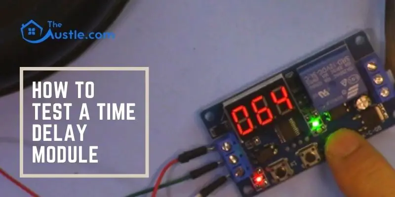
There are 20 steps about how to test a time delay module. These steps are very helpful indeed.
Step 1: Delay on Make Delay on Operate
During the process about how to test a time delay module, when the input voltage applied, the time delay begins. The output gets energy at the end of the time delay. To reset the time delay relay, the input voltage must be removed. Then de-energize the production.
Step 2: INTERVAL ON Interval
The output gets energy after the application of input voltage. Then the time delay begins. The production is de-energized at the end stage of the time delay. For resetting the time delay, the input voltage must be removed.
Step 3: OFF Delay on Release Delay on Break Delay on de-energization
The time delay relay accepts a trigger after the application of input voltage. The output gets energy after applying the trigger. The time delay begins after the removal of the trigger.
The production is de-energized at the end stage of the time delay. The time delay will reset after the application of the trigger. Then the production remains energized.
Step 4: One-Shot Momentary Interval
After the application of input voltage, the time delay relay is ready to accept a trigger. After the implementation of the trigger, the output receives energy. Then the time delay begins. During the time delay, the trigger ignores.
At the end stage of the time delay, the production is de-energized. The time delay relay is ready for another trigger.
Step 5: FLASHER (Off First)
After the application of the input voltage, the time delay begins. At the end stage of the time delay, the output gets energy. Then it remains in that condition for the time delay. At the end stage of the time delay, the production is de-energized. Then the sequence repeats until the input voltage remove.
Step 6: FLASHER (On First)
After the application of input voltage, the output gets energy. Then the time delay begins. At the end stage of the time delay, the production is de-energized. It remains in that condition for the time delay. At the end stage of the time delay, the output gets energy. Then the sequence repeats until the input voltage remove.
Step 7: ON/OFF DELAY
after input voltage, the time delay relay is ready to accept a trigger. After the trigger, the time delay begins. At the end stage of the time delay, the output gets energy. After the removal of the trigger, the output contacts remain excited about the time delay.
At the end stage of the time delay, the output is de-energized. Then the time delay relay is ready to accept another trigger.
Step 8: SINGLE SHOT FALLING EDGE
when the input voltage, the time delay relay accepts a trigger. Use of the trigger, the output remains de-energized. Then removal of the trigger, the output is energized. Then the time delay begins.
At the end stage of the delay, the production is de-energized unless the trigger is removed and re-applied before time out. The time delay will cause the output to remain energized indefinitely after the continuous cycling of the trigger.
Step 9: Retriggerable Single Shot
After the application of input voltage, the time delay relay is ready to accept a trigger. After the use of the trigger, the output gets energy, and the time delay begins. At the end stage of the time delay, the production is de-energized unless the trigger removes.
Then it is reapplied before time out. The output to remain energized indefinitely, after Continuous cycling of the trigger at a rate faster than the time delay
Step 10: TRIGGERED ON DELAY
After the application of input voltage, the time delay relay is ready to accept a trigger. After the use of the trigger, the time delay begins. At the end stage of the time delay, the output gets energy. Then it remains in that condition as long as either the trigger is applied.
The input voltage remains. If the trigger removes during the time delay, the output remains de-energized. Then the time delay is reset.
Step 11: REPEAT CYCLE (OFF 1st)
After the application of the input voltage, the time delay begins. At the end stage of the time delay, the output gets energy. It remains in that condition for the time delay. At the end stage of this time delay, the production is de-energized. Then the sequence repeats until the input voltage removes.
Step 12: REPEAT CYCLE (ON 1st)
After the application of input voltage, the output gets energy. Then the time delay begins. At the end stage of the time delay, the production is de-energized. It remains in that condition for the time delay. At the end stage of this time delay, the output gets energy. Then the sequence repeats until the input voltage removes.
Step 13: DELAYED INTERVAL Single Cycle
After the application of the input voltage, the time delay begins. At the end stage of the time delay, the output gets energy. It remains in that condition for the time delay. At the end stage of this time delay, the production is de-energized. Input voltage needs to remove to reset the time delay relay.
Step 14: TRIGGERED DELAYED INTERVAL
Single Cycle after application of input voltage, the time delay relay is ready to accept a trigger. While the trigger is applied, the time delay begins. At the end stage of the time delay, the output is energized.it remains in that condition for the time delay. At the end stage of the time delay, the production is de-energized.
Step 15: TRUE OFF DELAY
After the input voltage, the output gets energy. When the input voltage removes, the time delay begins. At the end stage of the time delay, the production is de-energized. Input voltage needs to apply for a minimum of 0.5 seconds to ensure proper operation. Any kind application of the input voltage while the time delay will reset the time delay.
Step 16: ON DELAY/ TRUE OFF DELAY
After the application of the input voltage, the time delay begins. At the end stage of the time delay, the output gets energy. While the input voltage removes, the production remains excited about the time delay.
At the end stage of the time delay, the output is de-energized. Input voltage applies for a minimum of 0.5 seconds for proper operation. Then reset the time delay
Step 17: SINGLE SHOT-FLASHER
After the application of input voltage, the time delay relay is ready to accept a trigger. While the trigger is applied, the time delay begins. Then the output is energized for the time delay. At the end stage of this time delay, the production is de-energized.
It remains in that condition for the time delay. At the end stage of the time delay, the output is energized. Then repeat the sequence until time delay completes. While the time- delay, the trigger is ignored.
Step 18: ON DELAY-FLASHER
After the application of the input voltage, the time delay begins. At the end stage of the time delay, the output is energized. It remains in that condition for the time delay.
At the end stage of this time delay, the production is de-energized.it remains in that condition for the time delay. At the end stage of the time delay, the output is energized. Repeat the sequence until the input voltage is removed.
Step 19: Percentage
After the initial application of input voltage, the output is energized, and the time delay begins. Time Delay is adjustable as a percentage of the overall cycle time. At the last stage of the time delay, the production is de-energized for the remainder of the whole Cycle.
Repeat the sequence until the input voltage removes. When the input voltage is removed and reapplied, the timing cycle will continue from where it left off while the input voltage remove.
Step 20: PERCENTAGE (NO MEMORY)
This is the last stage on How to test a time delay module. After the initial application of input voltage, the output gets energy, and time delay begins. Time Delay is adjustable as a percentage of the overall cycle time.
At the end stage of time delay, the output is de-energized for the remainder of the whole Cycle. Repeat the sequence until the input voltage removes. When the input voltage is removed and reapplied, the timing cycle will reset.
A 100% setting energizes the output continuously when an environment of 0% de-energizes the production continuously.
Conclusion
In this article, a detailed explanation of how to test a time delay module will help you more than earlier. Time delay modules are available as plug-in devices like plug-in control relays. However, they are also available, including base-mounted devices and direct IEC DIN-mounted controls.
Electronic, starter-mounted Time delay modules are also available. It can provide simple, reliable, and economic control. Adjusting the delay time is as simple as turning a knob.
It provides time-delayed switching to start a motor, control a load, or affect a process; industrial applications use time delay modules.
- How To Remove Pavers? 6 Easy Steps For You
- How To Fill Holes In The Yard From The Dog – 5 Easy Steps
- 13 Simple And Better Steps – How To Install A Radio In A Cat Skid Steer
- How To Fix Plastic Gas Tank On A Lawnmower – 7 Easy Steps
- How to Start A Bush Hogging Business Effectively in Best Ways
- How To Remove Purple Primer from Hands – 7 Easy Steps
- How To Get Rid Of Thorn Plants? 7 Best Ways